What pellet extruder output is needed for your application?
The maximum output of an extruder in terms of kg/hr or lbs/hr is a specification used in the industrial pellet 3D printing market. After several years of 3D printing experience, CEAD has found that it is deceiving and misleading to use the extruder output as a measure of printing speed and output capabilities during printing. After research and testing several variables, CEAD found that there are different limiting factors in determining the output of a large scale 3D printer. Based on these findings CEAD has set up this document in order to describe the actual needed extruder output for large scale 3D printing depending on the clients application, partsize and printing strategy.

3d printed mold
System limitations
There are several limiting factors in terms of output speed during printing. In table 1, an overview of the most influential factors during large scale additive manufacturing is presented.
| Factor | Description |
| Extruder output | Maximum output in kg/hr or lbs/hr |
| Cooling rate | Cooling rate of the extruded material |
| Machine movement speed | Movement speed of the machine during printing in mm/min |
| Nozzle size | Diameter of the nozzle in mm |
| Bead size | layer height and layer width in mm. |
Table 1
Extruder output
Extruder output is the maximum output the extruder can deliver. This is dependent on the material being used and the nozzle size being used. The specific weight of thermoplastic materials can differ hugely. For instance, Polypropylene has a specific weight of 900kg/m^3 and Arnite made by DSM has a specific weight of 1780kgm^3 (https://www.dsm.com/solutions/additive-manufacturing/en_US/products/fused-granulate-fabrication/arnite-am8527.html). This is an increase of 97% in weight with the same volume of material. Meaning that your extruder output is twice as high in terms of kg/hr while your volume output is not changing. Another factor in measuring extruder output is the understanding of the nozzle diameter during an output measurement. A smaller nozzle leads to a higher pressure inside the extruder. The extruder must be capable of delivering enough torque in order to deal with this pressure at a high output. A higher pressure also means more backflow inside the extruder, leading to less output. When measuring output of an extruder you will have a different specification when using a 4mm nozzle vs. a 10mm nozzle. The 10mm nozzle will give you a higher output. When comparing extruder capabilities it is good to understand under what condition the output for different suppliers has been measured.
Cooling rate
The cooling rate is how fast the material is capable of becoming stable enough for the machine to place another layer on top of the previous printed layer. Thermoplastics are by nature bad thermal conductors. They also contain a lot of heat energy after being extruded. This energy needs time to dissipate to the surrounding environment. The time it takes to become stable is dependent on the bead size and on the material thermal conductivity. The thermal conductivity can be improved by using for instance carbon fibres inside the material. Carbon fibre has excellent thermal conducting properties.
Machine movement speed
The maximum speed of a machine during printing while staying accurate. A robot is by nature less accurate and stable at higher accelerations and moving speeds than for instance a gantry based machine.
Nozzle size
The right nozzle size is selected for a certain bead printing size. When the nozzle sizes become smaller the material will flow faster through the nozzle in order to achieve a certain output. There is a limit in how fast the material can flow through the nozzle. This is dependent on the material and fibre content. This limitation is mostly present in nozzle sizes ranging from 1-4mm in diameter.
Bead size
The selected bead size (Layer width x layer height) has an influence on the cooling rate, movement speed, maximum part size and nozzle size. Especially the cooling rate is of huge influence with the beadsize because the cooling time is proportional to the square of the beadsize (dependent on the material). The cooling time has an influence on your maximum part size and movement speed. It also has an influence in the part details and printing time. Selecting the right bead size for your application is critical for large scale 3D printing. This parameter is the link between all other limiting parameters.
| Factor | Dependent of |
| Extruder output | Material specific weight and nozzle size |
| Cooling rate | Material thermal conductivity and bead dimensions |
Relation between bead size and other factors
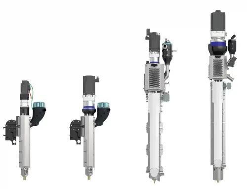
Choosing the right bead size is critical for a customer in order to determine if large scale 3D printing would fit their application and is economically feasible with the output that can be achieved during printing. CEAD conducted research on the effect of the beadsize on the printing speed. Throughout the research, a robot extruder (www.robotextruder.com) mounted on the AM flexbot made by CEAD (www.ceadgroup.com) was used.
This document focuses on rPet30%GF with a specific weight of 1350 kg/m^3. A fixed layer height of the bead of 2mm is used . With the help of graph 1 and 2, the effect of the bead width and the size of your part (layer print length) on the printing speed is explained.
Graph 1 indicates the needed movement speed of your machine in order to achieve a certain output. The bead sizes range between 6mmx2mm and 20mmx2mm. The green and the grey line are both limited in their extrusion speed. This has to do with the nozzle size needed in order to achieve a good bead at this size. When printing at higher speeds the extrusion speed of the material exiting the nozzle will become the limiting factor. Excessive extrusion flow speed will give you a poor surface finish and material properties. The larger bead sizes, need larger nozzles reducing the nozzle exiting speed of the material. The maximum output of the robot extruder is roughly 15kg/hr when printing with rPET30%GF. The maximum movement speed that has been used in this research on the AM Flexbot is 10 000mm/min. This graph indicates that the limiting factor during these trials is either the nozzle size (green and grey line) or the maximum output capability of the extruder (blue and black line).

Graph 1
However when we are trying to print with these kinds of outputs we face another problem. This could be the most limiting factor of large scale 3D printing: cooling rate. The larger the bead size is, the harder the heat can get out of the printed part. The reason being that a thermoplastic material is a bad thermal conductor. The cooling time is almost proportional to the square of the bead width. The actual formula is dependent on the material being used. In our second research we determined the cooling time needed for different bead sizes. This cooling time can be used in order to determine the mathematical relation between cooling time and bead width. The printing speed and output for a certain path length within 1 printing layer is directly related to the cooling time. The longer the path length, the longer it takes the machine to be back at the start of the layer, the longer the material has time to cool down. In graph 2 you can see the relation with the part size and the output of the extruder in kg/hour. The green and grey lines are limited by the movement speed of the machine (10 000mm/min). Meaning that with a beadsize of 6mmx2mm or 10mmx2mm, we can never reach an output of 15kg/hr since the machine cannot move fast enough. The black line indicates that our maximum layer length can be 13000mm before our extruder is becoming too small for the application. To give you an indication of the part size. You can print a tube with a wall thickness of 20mm and a diameter of 4138mm with this size extruder before it is becoming too small for your application.

Graph 2
Printing strategy
By changing your printing strategy for large scale 3D printing you can determine the right layer printing length for your application. Standard 3D printers and 3D printing slicing software, are slicing and printing a part in layers that are parallel to the horizontal plane. However for large scale 3D printing you can change the angle between the layers and the horizontal plane. In some cases it can be ideal to print with a 45 degree angle. Especially with a robot based system it is easy to change the printing angle.This enables the customer to print an enclosed box without the use of support material. In general, slicing under 45 degree angle also increases form freedom for the part and limits the usage of support structures.
Practical example
In order to explain the influence of the printing strategies and to give an indication of the layer printing length. We prepared an example part which indicates different printing strategies and corresponding layer lengths.

Figure 1: Mould design
In figure 1 we made an example of a large mould which can be printed with large scale additive manufacturing. Based on this part we will try to demonstrate 2 different printing strategies. The first strategy can be seen in figure 2. The part will be sliced at an angle of 45 degrees to the horizontal plane. This slicing ensures easier printing at lower speeds and reduces warping. It also shortens the printing path lengths. A very good recent demonstration of 45 degree angle printing has been made by the University of Maine. Showing that you can print large objects with a 45 degree printing strategy. A link to this demonstration can be found here: https://www.youtube.com/watch?v=Pt2epukih2k
As you can see in figure 2, a part with a reasonable size can be produced with this strategy and by using the robot extruder. The external path length is 7,6m which is still within the range of the extruder capabilities. With a larger extruder the material will reside in the extruder longer then desired which will cause the material to degrade. This is affecting material properties. So whenever possible, you would always want your material to stay in the extruder for the least amount of time as possible. Because of this it is also important to choose an appropriate extruder size.

Figure 2: 45 degree angle printing strategy.
The second strategy for printing such a part would be a slicing parallel to the horizontal plane. This would result in significant longer path lengths and in this case the capacity of the robot extruder would not be sufficient. The downside of slicing such large planes would be the warping effect. The longer your slicing plane in relation to the width would be, the more tension and warping will occur.
Conclusion: Extruder output needed?
Depending on your part size, printing bead width and printing strategy, the output of the robot extruder could suffice in your needs. If extremely large parts and large path lengths are required, the robot extruder might not have the output needed. In this case the client could have the possibility of combining 2 robot extruders into 1 melt bead (can be provided by CEAD group). This would give the customer more possibilities in the printing range, because the client can choose whether to use 1 or 2 extruders. Using an extruder that is too big with respect to the part could have the downside of exceeding the maximum residence time of the material , causing degradation of the material and in the worst case blocking of an extruder. The main conclusion being that the output of an extruder in terms of kg/hr is not a good measure whether an extruder suits your application. A lot of factors come into play when printing on a very large scale. Would you like to ask us some questions regaring your 3D printing application? Get in touch with us.